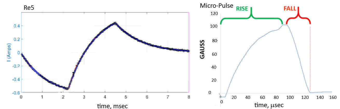
This post combines the preclinical results from a US company called Micro-Pulse and a very biophysical “letter to the editor” by a Danish company called Re5. The featured image of this post is a MicroPulse ICES waveform and one from Re5 supplemental data referenced in this post. It is assumed that the rise time of the magnetic field follows that of the current. Slew rate and wave form have always ben important to Micro Pulse. Re5 is making the case that controlling the rise time also controls the electric field and the ratio of the electric field to the magnetic field. Both companies sell a device for transcranial PEMF for brain health. Both have concern for the traumatic brain injury market. One company is a bit ahead of the other in terms of directing the PEMF.
Possibly important concepts
Targeted trans cranial electric and magnetic fields are used for healing.
Concept of parcellation
Destrieux C, Fischl B, Dale A, Halgren E. Automatic parcellation of human cortical gyri and sulci using standard anatomical nomenclature. Neuroimage. 2010 Oct 15;53(1):1-15. PMC free paper
The Re5 publication has some very biophysical thoughts that rely heavily on dividing the human brain into parcels and estimating the ratio of magnetic to electric fields in the white matter of there parcels. Why white matter might have to do with the diamagnetic nature of phospholipids of myelin addressed in the membrane leak post. . This site has addressed the ancient concern that magnetic fields from MRIs might orientate phospholipids in a way that causes membrane leaks, which it does not, as discussed in the membrane leak post.
Magnetic fields: cryptochrome and dimagnetic phospholipids?
Dufor T, Grehl S, Tang AD, Doulazmi M, Traoré M, Debray N, Dubacq C, Deng ZD, Mariani J, Lohof AM, Sherrard RM. Neural circuit repair by low-intensity magnetic stimulation requires cellular magnetoreceptors and specific stimulation patterns. Sci Adv. 2019. Oct 30;5(10):eaav9847. [PMC free article]
At least somewhat hinted by Tang 2026 main text and found in the reference section. Dufor 2019 was discussed in the Cry2 and transcranial PEMF post. The dimagnetic nature of phospholipids was discussed in the the membrane leak post.
Electric fields: galvanotaxis, electroporation, and electrophoresis
Antal A, and others…. Low intensity transcranial electric stimulation: Safety, ethical, legal regulatory and application guidelines. Clin Neurophysiol. 2017. Sep;128(9):1774–1809. [PMC free article]
Fig 1 offers a very nice diagram of how electric fields are established in the patients’ brains and force lines color coded for electric field strength. These authors claim that the electric fields are not strong enough to induce action potentials but can put holes in the membranes. Galvanotaxis / electrotaxis has a Wikipedia page that dose not leave the reader with rock solid definition. Electrophoresis is the movement of charged particles in an electric field. Perhaps transcranial electric fields just move charged particles between them, but at a potential difference that does not cause action potentials. .
Huang Yand others. Measurements and models of electric fields in the in vivo human brain during transcranial electric stimulation. Nat Commun. 2017;8:15292. [PMC free article]
This paper was referenced by the Tang 2026 Re5 publication. It contains more details on measuring electric fields in the human brain. This is a very in depth paper for further reading.
MicroPulse.com
The technology behind MicroPulse ICES was developed by Bob Dennis, a former NASA scientist. Bob has a healthcare professionals helping him develop protocols. Though the company is very biophysical, this in house publication is refreshingly void of potential mechanism of how the electric, and nor, magnetic fields operate. The only purpose was to demonstrate some benefit in a few patients. Never mind statistical significance, what would be meaningless in a small group.
ICES protocol
CAUTION: MICRO-PULSE ICES PRODUCTS ARE NOT PROVEN SAFE AND EFFECTIVE FOR ANY USE.
This post combines a self published ICES protocol for traumatic brain injury and a very biophysical “letter to the editor” published by the Danish PEMF device company Re5.
- Cortical Metrics – ICES PEMF – Pilot Study 3-30-2017 ICES PROTOCOL USED BY WILLIAM PAWLUK, M.D.
- Recovery was quantified using BrainGauge.
- DEVICE: ICES Model A9a modified to run one frequency only: 10 Hz (5 pulses per second) continuously. This stimulation pattern is identical to Mode #1 on the ICES models A9 and P2
- COIL PLACEMENT (still under investigation, not yet optimized) First Placement of Coils was coils on opposite sides, front and back of head. Second Placement of Coils was on opposite sides of head across the temples.Optional Placement of Coils was across the occipital lobes, side of head, coils on opposite sides of head.
- Stimulation was two hours every day at approximately the same time every day, to accommodate the subject’s schedule. Study continued for up to 3 months of daily use. All 8 subjects showed marked improvement within 6 weeks.
- Based on the study so far, the suggested treatment for any head injury, or multiple injuries is: one hour in First Placement, front and back of head, followed by one hour in Second Placement, across the temples, coils on opposite sides of head (2 hours total) every day, at approximately the same time every day.
- POWER SETTING: Begin with “L” (LOW) on Day 1 If no adverse reaction, raise to “M” (MEDIUM) on Day 2 If no adverse reaction, raise to “H” (HIGH) on Day 3, and keep on HIGH for the remainder
- Most people had a headache for the first 2 to 3 days. None of them were disabling and none of them required medication, or medical attention, even the severe TBI people.
- Typically the treatments would be daytime or evening every day. Treatment continued for up to 3 months
The results of individual experiences can be downloaded from DropBox…. TOJ is Temporal Order Judgement
Quick patient summary
- Mild TBI with issues with time perception and TOJ that were improved in 3 months and normal in 5 months
- Mild TBI with issues with TOJ that were improved in 6 weeks and normal in 3 months
- Mild TBI with issues with time perception that were improved in 3 weeks and normal in 3 months.
- Mild TBI with issues with all 8 functions except fatigue, which was not measured. All measured functions except TOJ were improved by 3 weeks. Normal or near normal at 1 month
- Moderate TBI with issues with time perception, TOJ, connectivity, and fatigue.Time perception and TOJ remained severely compromised even after 5 weeks.
- Moderate TBI started the study with very compromised TOJ, time percept, and connectivity. Fatigue score was in the normal range. At the 2week end of his patient’s experience with ICES TOJ, time percept, and connectivity were normal and the fatigue score indicated a compromised state.
- Moderate TBI started the study with compromised TOJ and connectivity. At the end of 2 weeks all functions normal or near normal.
- Severe TBI speed, TOJ, and corticocal metric functions were all that was measured and they were very poor. At the end of the month,all eight functions were normal or near normal.
This non peer reviewed study was not meant to be mechanistic in any way shape, or form. As long as there are no adverse events and the patients’ conditions are improved, mechanisms are secondary. MicroPulse has always been very strong on the physics. A recent Re5 “Letter to the Editor” is also strong into physics. One has to go into the supplemental section to get the real education.
re5.com
This Danish company has been testing and marketing a very targeted brain PEMF stimulator. Their official website does a pretty good job of documenting the many studies that makes them who they are as a company. They don’t seem to do that great of a job describing the physics on their official website. Most users would probably not appreciate it anyway.
Re5 the 2026 letter to the editor publication
Tang D, Deng ZD, Nummenmaa A, Ludwig R, Noetscher G, Makaroff S, Bizik G. Electric and magnetic field characteristics of the Re5 brain stimulation system. Brain Stimul. 2026 Mar 14;19(3):103074. PMC free paper
a) Positioning of the Re5-NTS array system with seven coils – sagittal view. This panel shows the placement of the coils. Could this be a guide for ICES users? ICES results were encouraging for matters of TOJ.
b) Battery-powered, activated by pre-programmed ID card access stimulator (pulse generator) and its physical dimensions.
c) View of the complete Re5-NTS system. More positioning of the coils.
d,e) Volumetric plots – cross-section views – of the magnetic and electric field magnitudes in the head for subject #1; maximum field values just outside white matter surface are reported in the same figure. The Re5-NTS system is operating at standard conditions. Note that panel d is the magnetic field and panel e the electric field, which is more spread out than the magnetic field.
f) Surface plot of the electric field magnitude just outside white matter surface for subject #1. The field is normalized by its maximum value reported in the same figure. The Re5-NTS system is operating at standard conditions; coil current directions are shown in the figure. This time the electrical field heat map is shown on the surface of the brain.
g-i) These panels examined the electric fields, magnetic fields, and ratios thereof in the frontal, temporal, occipital, limbic, parietal, insular cortexes.
Magnetic to Electric field ratios and parcels…

On the right we have a small snipping of Fig S5 along with what these parcels of the human brain correspond to. An attempt was make to assign regions to these parcels according to a table in the supplemental data section. Note that we do not see error bars in these plots. We do not know how much variability exists in these data. Transcranial magnetic stimulation does one thing and AC electrical stimulation does another thing? White matter is given a lot of press.
The desire seems to be have more magnetic field influence than electric field influence. It might be good to take the comments from the supplemental section of Tang 2026 back to Maxwell’s equations.
Maxwell’s equations and the Re5
Electric fields arise from charged particles. Magnetic fields arise from spinning charged particles, such as unpaired electrons. A hydroxyl bond, -OH, might have an electrical dipole moment because electrons are pulled more towards the nucleus of the oxygen than the hydrogen.

From the Physics Handbook on Maxwell’s Equations and the supplemental of Tang 2026
| equation | law | Physics Handbook comments | Re5 Supp link |
|---|---|---|---|
| ∇ ⋅ E = ρ/ε0 | Gauss’s law | + and – charges, just like numbers Electric field lines diverge from positive charge and converge on negative charge | ρ is the quantity of charge per unit volume, measured in the SI system in coulombs per cubic meter (C⋅m−3) is the value of the absolute dielectric permittivity or permittivity of free space, the electric constant, ε0 = 8.8541878188(14)×10−12 F⋅m |
| ∇ ⋅ B = 0 | No one’s law | there are no magnetic monopoles, as field arises from spinning electrons. Magnetic field lines neither converge nor diverge (have no beginning or end). | Tang had nothing to say about this law. Diamagnetic phospholipids tend to align with static magnetic fields as a putative therapeutic mechanism Ammann C, Soto-León V. Home-based transcranial static magnetic field stimulation – concept, development, and clinical applications: IFCN handbook chapter. Clin Neurophysiol Pract. 2026 Apr 9;11:282-293. PMC free paper |
| ∇ × E = − ∂B/∂t | Faraday’s law | Electric field lines don’t curl…except when the magnetic field changes. | the induced electric field strength is proportional to the temporal rate of change of the magnetic flux density. While 𝑩 is proportional to the current, the induced electric field magnitude scales with 𝑑𝐼/𝑑𝑡, the rate of change of the coil current. In other words, the induced E-field is proportional to the slope of the current waveform and is zero if the current is kept constant. |
| ∇ × B = μ0ε0 ∂E/∂t+ μ0J | Ampère’s law | Magnetic field lines curl around electric current… and also curl when the electric field changes. | The magnetic field strength generated by an induction coil follows Ampère’s law; the magnetic flux density 𝑩 is directly proportional to both the input current 𝐼 and the number of turns 𝑁 in the coil. In the Re5-NTS, this relationship is expressed as ‖𝑩𝒊𝒏𝒔𝒊𝒅𝒆‖ = 𝜇0𝑁𝐼/𝑙, where 𝜇0 is the permeability of free space and l is the axial length of the coil. Although the input current of the Re5-NTS is low, the very large number of turns (3,500) dramatically increases the relative magnetic field magnitude both inside and outside the coil |
Some comments from the supplemental text in bullet points
- “In other words, the induced E-field is proportional to the slope of the current waveform and is zero if the current is kept constant.
- The B-field magnitude is only proportional to the current itself and is held at a constant when the current is not time varying. This relationship explains why conventional TMS employs very rapidly pulsed currents (with rise times on the order of 100 μs or even
- less) to generate sufficiently strong electric fields.
- In comparison, the huge Re5-NTS’s winding inductance of 250 mH lengthens the rise time, resulting in a lower current rate of change and thus a lower electric field magnitude as compared to the magnetic field magnitude.
- On the other hand, the induced electric field 𝑬 arises from Faraday’s law of electromagnetic induction ∇ × 𝑬 = −𝜕𝑩/𝜕𝑡, establishing that the induced electric field strength is proportional to the temporal rate of change of the magnetic flux density. While 𝑩 is proportional to the current, the induced electric field magnitude scales with 𝑑𝐼/𝑑𝑡 , the rate of change of the coil current.
- In other words, the induced E-field is proportional to the slope of the current waveform and is zero if the current is kept constant.
- The B-field magnitude is only proportional to the current itself and is held at a constant when the current is not time varying.
- This relationship explains why conventional TMS employs very rapidly pulsed currents (with rise times on the order of 100 μs or even less) to generate sufficiently strong electric fields.
- In comparison, the huge Re5-NTS’s winding inductance of 250 mH lengthens the rise time, resulting in a lower current rate of change and thus a lower electric field magnitude as compared to the magnetic field magnitude.”
𝜕𝑩/𝜕𝑡, the slew rate and ICES, has been discussed in a previous post.
Back to traumatic brain injury…
Both Re5 and Micro-Pulse device companies are calling into question the high power PEMF companies that have a high slew rate and their transcranial use.
Leave a Reply